Hi Everyone -
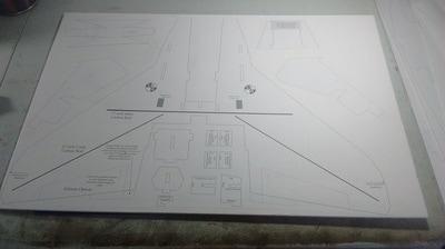
As already mentioned in the first article of this series, it took the better part of four (4) sheets of 20" x 30" DTF to build this Mig-35B including the KF4 airfoils. Due to the way Stephan designed the NAMC planes (all of which are now available at Parkflyers International website), the parts were easy to cut out and lay out on the sheets to minimize waste. Only one part, the main wing plate needed to be altered somewhat to allow it to fit. In the following pictures, you can see how I chose to lay out the parts.
I know it is a bit difficult to see with so much white, so in order as the pictures appear below, I will describe how I laid out the parts.😊
- sheet 1 includes the canopy, wing plate, all the smaller pieces you can see in the middle like bulkheads, motor mount reinforcements, motor mount and canopy support. It also includes the elevons. You will note I cut the top part of the LERX (leading edge root extensions) so that I could fit the wing plate on the sheet and keep the wing in one piece;
- sheet 2 is the top KFs, this actually only used about 1/2 the sheet, I saved the rest of the sheet for use for other KFs on other builds;
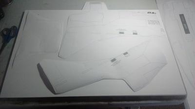
- sheet 3 includes all the fuselage outer pieces and the bottom KFs; and
- sheet 4 includes the nacelle/side piece/vertical stabs, the back plate and the spine structure for forming the fuselage/nose.
I'm sure there are lots of ways to lay out the pieces, this just seemed to make sense to me and only required a small modification to the wing plate. The small piece of the LERX was glued on with epoxy after the pieces were cut out.


Cutting the foam
I left all the paper on the foam while cutting out the pieces to prevent leaving glue residue on the bare foam which makes sanding and finishing harder later as I have discovered with KF airfoils in the past.
What I did learn is that I have to be very careful when applying the glue I use to secure the plans to the foam while cutting out the pieces. I use this glue shown below (Amazon link here).

What I found happened was if I got too much glue in areas, it would soak through the paper on the DTF and make removal of that much more difficult, however I did find a solution for that which I will discuss in the next article of this series.
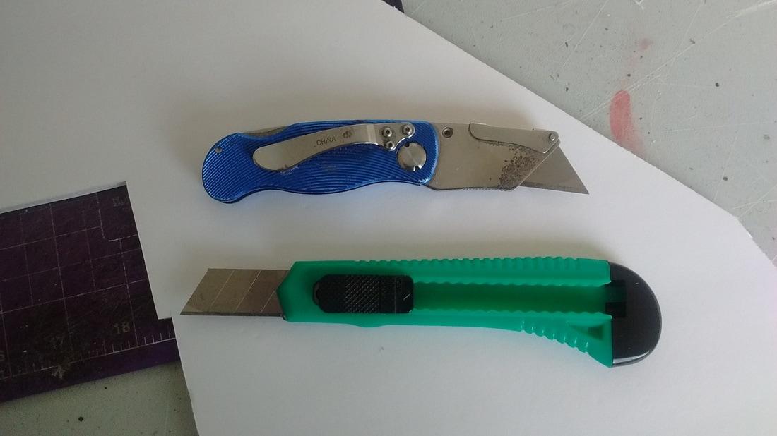
I have had lots of experiences cutting out KFs in the past, which are mostly straight lines, so never had any problems using the blue knife shown in the picture below which is my preferred knife for cutting out parts of planes. However, as I got cutting the pieces out with lots of angles, small tab slots, etc, I found I was at times crushing the foam and the cuts were not as clean as I would like. I tried the green style of knife and it seemed to work much better. Although impossible to tell with the naked eye, it felt like the blade was a bit thinner. Additionally, as the tip got dull, I could snap it off and have a fresh, sharp tip.
Cutting through essentially three sheets of paper (the plans plus the paper on both sides of the foam) plus 4.5 mm of foam dulls the blades very quickly and then will start again to tear or crush the foam. I had to snap the blades off pretty regularly during this build, so that is something to watch for, otherwise a dull blade can make a real mess of the edge of the parts.
DTF with the paper left on is 5 mm thick, with the paper removed on both sides, it is 4.5 mm thick. So when I cut out any slots, I cut along the inside of the lines to try and help with the fit. In hind sight, I learned that if I knew that bare foam was going into a slot that I probably need to cut the slot a little narrower, otherwise the fit was not as tight. DTF with the paper off can be pinched and shaped easily, so having a tab that is a bit too big for a slot is much easier to fix than having a tab that is too small for a slot and would make dry fitting much easier and straighter.
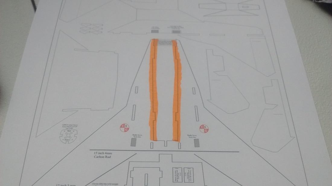
Since I removed the paper from the fuselage, the other lesson I learned is that in future builds, I need to add about 1.5 mm to each side of the inner part of the wing plate where it will meet the fuselage (highlighted in orange in the picture below). As mentioned above, the paperless DTF is only 4.5 mm thick as opposed to 6 mm like MPF or Depron, so when I was mating the wing plate and fuselage, it was a bit tricky and the back part of my fuselage is a bit off from what I would normally like because there was a gap between the wing plate and the fuselage.
Since I removed the paper from the fuselage, the other lesson I learned is that in future builds, I need to add about 1.5 mm to each side of the inner part of the wing plate where it will meet the fuselage (highlighted in orange in the picture below). As mentioned above, the paperless DTF is only 4.5 mm thick as opposed to 6 mm like MPF or Depron, so when I was mating the wing plate and fuselage, it was a bit tricky and the back part of my fuselage is a bit off from what I would normally like because there was a gap between the wing plate and the fuselage.
Paper removal
After a couple of discussions with Peter, I decided that the paper would be completely removed from all the fuselage parts including the inner structure, the canopy, the motor mount, motor mount reinforcements and partially removed from the wing plate and nacelle/horizontal stabilizer pieces.
I learned a few lessons while doing the paper removal that I will discuss in the next article.
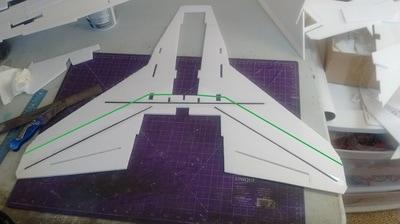
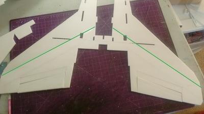
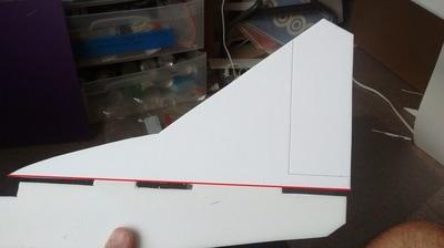
In these pictures, you can see on the wing plates that I left the paper on behind where the trailing edge of the KF would be or essentially behind the green lines. First picture on the left shows bottom of the wing plate, picture in the middle shows the top of the wing plate. On the nacelle/side plate/vertical stab piece, I left the paper on the vertical stabilizer for strength and removed it everywhere below the red line.
After a couple of discussions with Peter, I decided that the paper would be completely removed from all the fuselage parts including the inner structure, the canopy, the motor mount, motor mount reinforcements and partially removed from the wing plate and nacelle/horizontal stabilizer pieces.
I learned a few lessons while doing the paper removal that I will discuss in the next article.
In these pictures, you can see on the wing plates that I left the paper on behind where the trailing edge of the KF would be or essentially behind the green lines. First picture on the left shows bottom of the wing plate, picture in the middle shows the top of the wing plate. On the nacelle/side plate/vertical stab piece, I left the paper on the vertical stabilizer for strength and removed it everywhere below the red line.
The paper was left on the elevons and the back plate for strength.
All paper where applicable was removed before any reinforcement was installed. As you can see in the middle picture above, with the paperless foam being only 4.5 mm thick, I cut the foam out completely in the slot where the reinforcement was going before securing the reinforcement. What I didn't want to have happen is securing the reinforcement first with epoxy and then try to remove the paper, it would have been very difficult with the paper saturated with epoxy to remove the paper cleanly.
Reinforcement
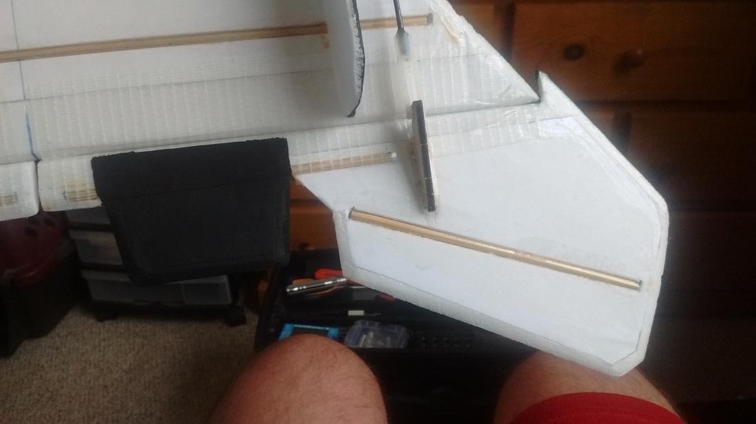
I used the standard wing reinforcement in this Mig-35B that is recommended, a 15" section of 4 mm carbon rod for the main spar and two 12" sections of 3 mm carbon tube for the "legs" or the parts that go down the wing as you can see more closely in this larger picture below.
All paper where applicable was removed before any reinforcement was installed. As you can see in the middle picture above, with the paperless foam being only 4.5 mm thick, I cut the foam out completely in the slot where the reinforcement was going before securing the reinforcement. What I didn't want to have happen is securing the reinforcement first with epoxy and then try to remove the paper, it would have been very difficult with the paper saturated with epoxy to remove the paper cleanly.
Reinforcement
I used the standard wing reinforcement in this Mig-35B that is recommended, a 15" section of 4 mm carbon rod for the main spar and two 12" sections of 3 mm carbon tube for the "legs" or the parts that go down the wing as you can see more closely in this larger picture below.

In the back plate, elevons and vertical stabilizers, I used bamboo skewers to help provide strength even though there was paper there as well.
When making the grooves to accept the reinforcement where I knew the paper was going to stay on both sides of the foam, I was very careful not to cut the paper on the bottom side. Once the score was made, the foam was easy to remove cleanly and left behind a very clean, snug channel in which to install the reinforcement. As mentioned already above, since the foam with paper removed is only 4.5 mm thick, I just cut the foam out completely to keep the slot clean. When I glued the reinforcement in, I always ensured I put wax paper underneath the foam so I didn't glue the piece to the table.
Where all reinforcements were made, I used epoxy and weighted the pieces down with heavy books and left them overnight. I did this not only to ensure that the reinforcements were well bonded, but also to ensure the foam was as flat as possible where the paper was left on. Sometimes, DTF will have slight curves in it depending on the tension of the paper on one side as opposed to the other. By putting weight across the foam while the epoxy was drying, it shaped the paper and foam so that it was very flat and true once everything was dried.
Hinging control surfaces
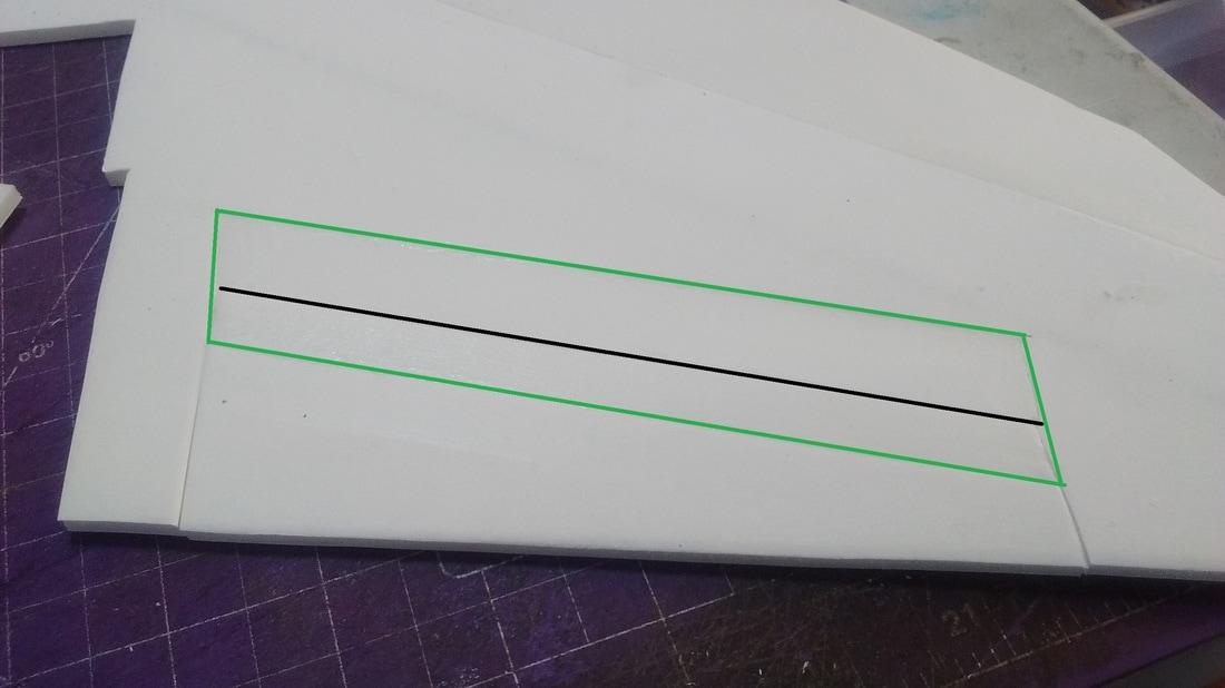
Again on Peter's recommendation, I removed about 1/2" of paper on either side of each hinge line of the control surfaces to ensure good bonding on the bare foam. Here is an aileron for example, the black line indicates where the actual hinge line is, the area outlined in green is where the paper was removed. Before applying the hinge tape, I sealed the edge of the paper with glue, scraping away the excess with scrap foam to ensure this was sealed before tape was applied. This would serve to not only make it more difficult for the tape to pull the paper off, but also to seal the edge to prevent water from getting under the edge of the paper. More on this in the next article in this series.
Where all reinforcements were made, I used epoxy and weighted the pieces down with heavy books and left them overnight. I did this not only to ensure that the reinforcements were well bonded, but also to ensure the foam was as flat as possible where the paper was left on. Sometimes, DTF will have slight curves in it depending on the tension of the paper on one side as opposed to the other. By putting weight across the foam while the epoxy was drying, it shaped the paper and foam so that it was very flat and true once everything was dried.
Hinging control surfaces
Again on Peter's recommendation, I removed about 1/2" of paper on either side of each hinge line of the control surfaces to ensure good bonding on the bare foam. Here is an aileron for example, the black line indicates where the actual hinge line is, the area outlined in green is where the paper was removed. Before applying the hinge tape, I sealed the edge of the paper with glue, scraping away the excess with scrap foam to ensure this was sealed before tape was applied. This would serve to not only make it more difficult for the tape to pull the paper off, but also to seal the edge to prevent water from getting under the edge of the paper. More on this in the next article in this series.
Prepping the edges for sanding
I like to sand the trailing edge of my wings, the leading and trailing edges of my vertical stabilizers, elevons, horizontal stabilizers and the prop slot to not only make my planes look nice, but also to help make them slipperier through the air. Where the paper had been left on, this was a bit of a tedious process, but I think well worth it.
I like to sand the trailing edge of my wings, the leading and trailing edges of my vertical stabilizers, elevons, horizontal stabilizers and the prop slot to not only make my planes look nice, but also to help make them slipperier through the air. Where the paper had been left on, this was a bit of a tedious process, but I think well worth it.
As you can see in the picture below of one of my elevons, anywhere I was going to sand the edge, I removed about a 1/4" width of paper, then sanded, then sealed the edge of the paper with glue. I like to do this when the pieces are flat before the air frame is assembled, I just find it much easier to do this way. I also sand the fuselage assembly so that it is ready to go before mating it to the wing plate.
Air frame assembly
Once all the prep work was done as described above, the air frame went together well. I did have to be more careful handling the wing plate, fuselage and nacelles where all the paper had been removed as these were still flexible and paperless DTF while easy to sand can also be dented and marked up very easily if it isn't handled carefully. Due to my cutting some of the slots and tabs were not as tight as I would have liked them, I did take extra time to ensure everything was lined up and true, pinning and taping as required. Other than that, it was just the same as building with MPF or Depron.
Shaping and sanding
I shaped and sanded this plane like I do all my others, the paperless DTF can be trimmed quite easily as long as I used a new, sharp blade, otherwise the foam could pull and tear easily. It sands very nicely, although in areas like the nose and canopy, I did have to be careful not to sand too much off lest the foam become too thin and delicate.
After the plane had been completely sanded and the dust cleaned off my plane by simply using the brush attachment on my vacuum, I applied the Minwax as described in part 2 of this series of articles. Once applied, I left the Minwax to completely dry overnight before applying any paint.
Painting
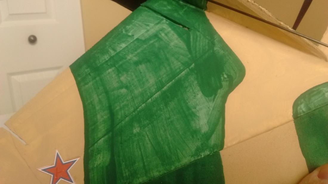
I use inexpensive water based acrylic paints that I get from the dollar store, Walmart, etc. I knew I would be OK painting where the paper was left on as I had sealed it with the Minwax. I did not have any of the paper bubble or separate, however since I had created a waterproof barrier on the paper with the Minwax, the acrylic paint did not work out as well as it does on raw foam. As you can see on this portion of one of my wings where the paper was left on and Minwax applied, up close it isn't the best paint job I have seen, but in the air, I don't think it will matter too much.
Once all the prep work was done as described above, the air frame went together well. I did have to be more careful handling the wing plate, fuselage and nacelles where all the paper had been removed as these were still flexible and paperless DTF while easy to sand can also be dented and marked up very easily if it isn't handled carefully. Due to my cutting some of the slots and tabs were not as tight as I would have liked them, I did take extra time to ensure everything was lined up and true, pinning and taping as required. Other than that, it was just the same as building with MPF or Depron.
Shaping and sanding
I shaped and sanded this plane like I do all my others, the paperless DTF can be trimmed quite easily as long as I used a new, sharp blade, otherwise the foam could pull and tear easily. It sands very nicely, although in areas like the nose and canopy, I did have to be careful not to sand too much off lest the foam become too thin and delicate.
After the plane had been completely sanded and the dust cleaned off my plane by simply using the brush attachment on my vacuum, I applied the Minwax as described in part 2 of this series of articles. Once applied, I left the Minwax to completely dry overnight before applying any paint.
Painting
I use inexpensive water based acrylic paints that I get from the dollar store, Walmart, etc. I knew I would be OK painting where the paper was left on as I had sealed it with the Minwax. I did not have any of the paper bubble or separate, however since I had created a waterproof barrier on the paper with the Minwax, the acrylic paint did not work out as well as it does on raw foam. As you can see on this portion of one of my wings where the paper was left on and Minwax applied, up close it isn't the best paint job I have seen, but in the air, I don't think it will matter too much.
Component selection
As I was going into uncharted territory with respect to the weight that would be added to my build with the paper, Minwax and extra reinforcement, I purposely chose some lighter components and I'm glad I did, otherwise I would not have stayed within the "sweet spot" weight I like of between 21 and 22 oz. I chose the DYS 2208/7 2600 Kv motor with Master Airscrew 6x4x3 prop as this combo is about 7 gr/.25 oz lighter than the 2212 motors I have used in either 2200 or 2700 Kv. I still had to use a 40A ESC with this motor, so no weight saving there.
As I was going into uncharted territory with respect to the weight that would be added to my build with the paper, Minwax and extra reinforcement, I purposely chose some lighter components and I'm glad I did, otherwise I would not have stayed within the "sweet spot" weight I like of between 21 and 22 oz. I chose the DYS 2208/7 2600 Kv motor with Master Airscrew 6x4x3 prop as this combo is about 7 gr/.25 oz lighter than the 2212 motors I have used in either 2200 or 2700 Kv. I still had to use a 40A ESC with this motor, so no weight saving there.
Shortly after I started flying this plane, I started to experiment with a lighter quad racing motor (RC Timer FR2205 2550 Kv) which saved me another 12 gr/0.4 oz.
I have had some good luck on other builds using RC Timer 5 gr nylon gear servos for the ailerons and rudders. Here you can see two of them as my rudder servos. I still use the RC Timer 9 gr servos from our parts list for the elevons since those get so much use and abuse in the prop wash.
I recently shot this video describing my choice of servos in my park jets and the success I have experienced using lighter 5 gr servos.
By using four of the 5 gr servos, I saved another 24 gr/.85 oz of weight for a total saving with the lighter motor of 31 gr/1.1 oz. My current weight of this plane with a 2200 3S battery is 21.4 oz/607 gr.

Build summary
Overall, I am very pleased with how this build turned out. I think I accomplished the goals of having a plane that looks really good while still having good strength without being too heavy. Of course I will have to be careful handling the fuselage and nacelle areas and will only be able to assess the strength and durability of the build with considerable flight testing.
In comparison to building with Depron or MPF, this build took me about 50% more time because of some of the tedious processes required for removing the paper and treating the paper remaining so that it would be strong, water proof and durable. Of course since it was the first time I was trying many of these methods, that probably slowed things down a bit, but I did learn a lot which was another of my goals.
In the next article, I will discuss some lessons learned in the paper removal to keep the plane light, strong and hopefully keep the paper from peeling off as times goes on. This was some of the most tedious work when building with DTF, but I think from input I got from Peter and some other guys at my flying field, it is worth the extra time, patience and effort.😊
Park Jet noise...the "other" sound of freedom😎
Cheers,
Scott
No comments:
Post a Comment