I am passionate about building and flying scratch built foam park jets and passing on my experiences and lessons learned from more than five years of experience. Blog is purely based on my own opinions and experiences. If you have questions, please e-mail me at scott.parkjet@gmail.com. Park Jet noise...the "other" sound of freedom :) Happy flying! Cheers, Scott
The pages of the F-18 V3 plans printed at 91% to get the templates for the LERX (leading edge root extension), dogtooth at the wing tip and vertical stablizer are 4 and 6-9. LERX on page 6&7, dogtooth on page 9, vertical stabilizer on pages 4 and 8.
Dimensions of my KF airfoils on the top.
Measured along the fuselage from the back of the KF to the front of the LERX, approximate 14 and 1/4".
Measured at the wingtip (will be same top and bottom).
Measured on the bottom KF along the nacelle, approximate 4".
Important note: Whenever modifying and installing KF4 airfoils (airfoil top and bottom), it is very important to ensure that the trailing edges match top and bottom (or as close as you can possibly get them). If one of the trailing edges is further back than the other by even a couple of mm, it can cause your plane to climb or dive as speed increases. Better to cut them a bit bigger and trim down as you need to rather than cut them too small as you will probably have to cut another anyway😊
Modified aileron dimensions. I started at the inside per the plans, where the green arrow is pointing is 2", blue arrow 1 and 1/8" and white arrow 6".
As mentioned in the video, although I modified the vertical stabilizers, I still used the elevon and rudder dimensions from the stock plans.
The "missile rails" are 6" long and 3/8" deep, made with two pieces of scrap foam glued together with a half a popsicle stick for extra strength along the bottom.
I sanded and shaped the rails to look scale after looking at several F/A-18 pictures like this one😎
On both the F-18 V5s, my CG has ended up considerably further ahead than "stock" or dead centre on the "CG spectrum" RC Powers puts on their V5 plans. As mentioned in the video, mine ended up 1 and 1/8" ahead of stock. Toothpick shows where stock CG is, "T" pin shows where my F-18 V5 balances best.
Throws
For reference, here are pictures of where I held the ruler to measure my throws (all measurements are one way). As mentioned in the video, I don't fly with a whole lot of expo, 15% in the pitch and roll and 20% in the yaw. I would always start off with what RC Powers recommends and adjust from there to suit your flying style😊 Elevons, 1" of travel in the pitch and 3/4" of travel in the roll.
Ailerons - 5/8" travel.
Rudders - 3/4" of travel.
I hope you have found this video and blog post helpful, I really enjoy the F-18 V5, it is a real "sports car" of park jets and after the F-22 V5 my favorite of the V5 lineup I have built and flown thus far.
If you have any questions, please don't hesitate to leave them in the video comments on YouTube, down below or you can e-mail me at scott.parkjet@gmail.com.
This blog post is in support of the video I shot discussing the RC Timer FR2205 2550 Kv motor. I have been using this motor for about seven months now, it is the first quad racing motor that I have experimented with for use in a park jet.
Here is the video
Here are more links to some of the gear discussed in this video -
Motor test spreadsheet with further prop test data. Please go to the page marked "quad racing motors" to get the data on this and the other two quad racing motors I am currently evaluating.
This link is to a list of quad racing motors I will be testing, I already have the first three on the list and I'm waiting for the rest as well as some 5" tri blade quad props to evaluate for possible use in park jets.
If you are interested in bench testing of many different quad motors with props other than what are normally used on props for use in your park jet, flying wing, etc, please check out rcplanepirate's YouTube channel.
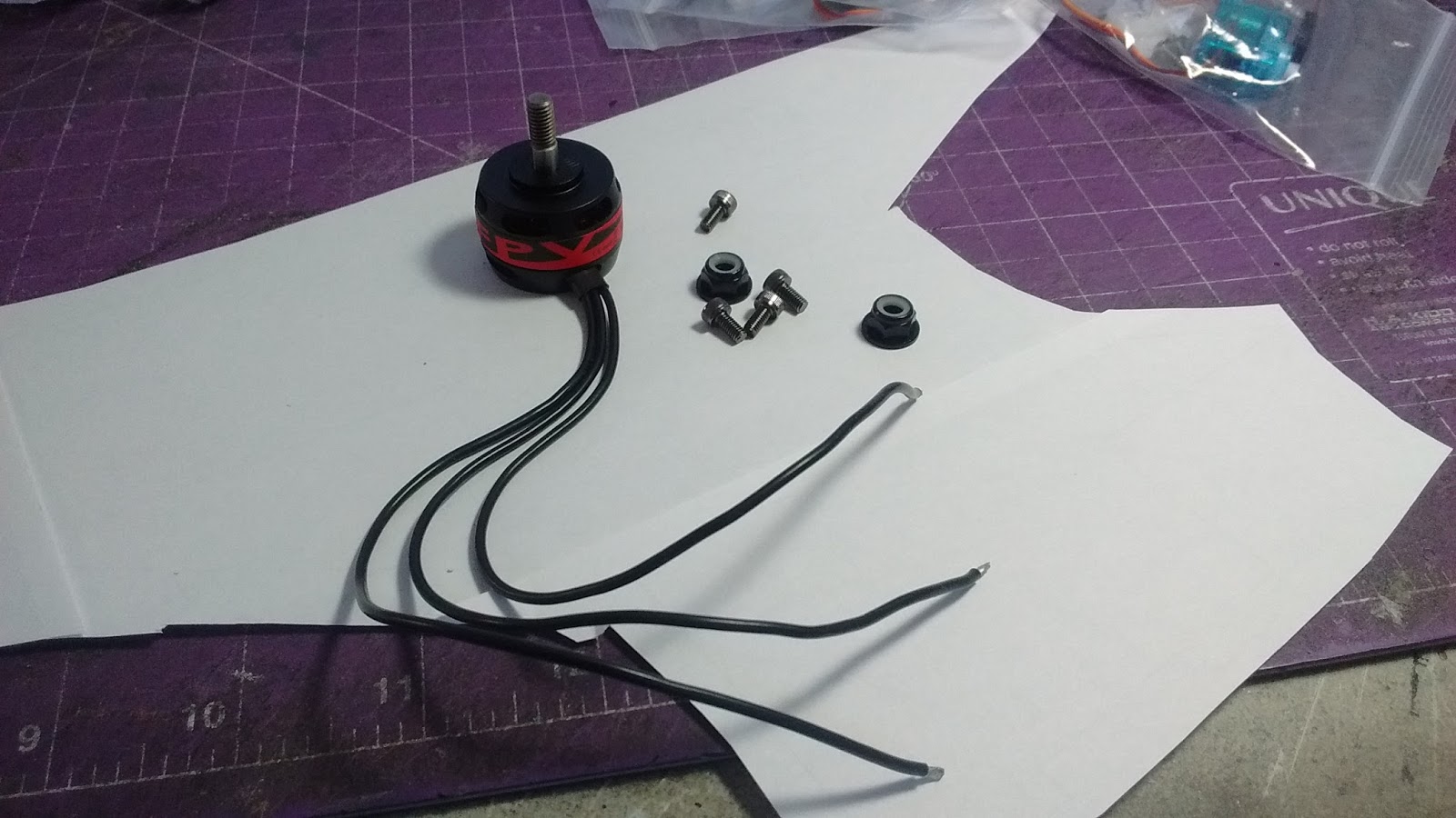
Still pictures of the FR2205 2550 motor showing more closeups. First picture shows what comes in the box from RC Timer.
Standard X mount secured to the motor as linked above.
Closeup showing the large cooling holes, I have pushed this motor up to 32A in warmer summer weather (28C/82F) and it ran very cool without problems.
Important note - in the first couple pictures you see a red label on the motor. This label is made of an almost vinyl kind of tape and it came off in mid air after a few flights, scaring the living daylights out of me!😓 Fortunately it didn't foul the motor or the prop, but lesson learned, I will now remove this label from all of these RC Timer quad motors before flying in the future to prevent problems.
Last evening and today were busy getting the plans taped together, doing some measuring, drawing and even quite a bit of math...brain is tired now!😖 I think I have the vast majority of the work done to satisfy my planned modifications, so it will be much easier to start cutting foam and get building😊
I'll try to keep this organized and explain in detail what I did as well as why and how I did it, so this will be a bit of a lengthy post, but should be lots of pictures for distraction😉 Either way, you might want to grab a snack and a beverage, or read it in small chunks! This is normally the longest part of the build process for me when I am doing several mods on a plane, lots of measuring, figuring, drawing, redrawing, etc, but once I am happy with it, the rest goes along a lot quicker and smoother😊
I'll start with the wing plate since that is the most detailed and required the most measuring and drawing to accommodate my planned modifications.
One of the things common to all the V5s I have built is the wing plate is in two separate identical pieces. I prefer to tape these together first before putting them on the foam and cutting, especially if I am going to make modifications as you can see above in this picture. I have roughly laid out my carbon reinforcement ahead and behind the prop slot and along the elevon hinge line. One main difference between this and the F-22 is that she has a little extra "junk in the trunk" behind the wing as it is much wider than the F-22 V5.
In this current size, while I could lay it down on a 20x30" sheet of Dollar Tree foam (DTF) to get the 27" wingspan in one piece, it is far too long and needs to be cut in a couple of spots. I chose to draw lines here in front where the LERX (leading edge root extension starts to angle back more dramatically. This piece will get glued back to the main wing plate at a later point in the build once other things have been completed with the main wing plate.
In the rear, it made sense to cut off the elevons as I will be making those out of Depron anyway.
This will leave me with a main wing plate piece that is about 19" long, so easy to fit across the 20" width of a full sheet of DTF and have that all one piece.
Motor mount/prop slot mod, etc
As I mentioned in part 1 of this series, one of the mods I will make is to move the motor further forward by 1", primarily to compensate for the weight of the paper on the DTF behind the trailing edge of the KF and also hopefully to help the plane be more balanced and rotate more easily in all three axes.
There is a lot going on in this picture above, so I'll try to make sense of it. Originally, when I drew the sides of the prop slot, I had forgotten to widen it out so that it will be even with the outside parts of the "engines/nacelles" underneath. The black dashed "-" lines indicate where that will be, drawn by lining up the slots fore and aft on the wing plate to see where those will be. The lines that are "squiggled" out in black were my original lines and it made for a very narrow prop slot, maybe 6 and 3/8" which caused me to remember I could widen it out.
Hopefully you can see where I moved the motor mount forward 1" and also trimmed 3/8" off the leading edge of the prop slot to accommodate shorter quad racing motors. I always like the back of my prop slots to be a straight line, so drew that in accordingly. Gives my prop lots of room to "breathe" and perhaps it is not aesthetically pleasing, but hopefully gives me best performance from my prop and motor.
You can see where I put my carbon ahead of the motor mount, I will be using a piece of 3mm carbon tube as shown below. It is recycled out of a previous plane, so I need to remove the foam and glue residue before it goes into this plane. If you look to the right of the motor mount area below the carbon tube, I have drawn a small 1/4" square, this will accept a 1/4" tab from the top of the fuselage. I made this change so that nothing would interfere with the carbon tube, it is primarily for alignment of the top of the fuselage, not for strength, so should be adequate. If you look at the far right, I also modified the slot that will accept one of the tabs on the "engines/nacelles" to accomplish the same thing. I will place the carbon tube so that it runs right through the dead center of the "CG spectrum" that RC Powers puts on their V5s. This way I know that where this tube is will be my starting CG point for the maiden flight.
Reinforcement of the wing plate
As you can see in this group of pictures, I will be using carbon to reinforce the wing plate in three areas, a 13" piece of 3mm carbon tube ahead of the prop slot as shown above. I'm hoping that since this will be "locked in" under the KF4 airfoils it will give sufficient strength without adding the extra weight of 4mm carbon rod. Plus I already had a piece that fit perfectly recycled from another plane😉
For the main wing spar, I am using a 25 and 1/2" piece of 4mm carbon rod for maximum strength across the widest part of the wing, again, this piece was recycled from another plane, glue and foam residue need to be removed.
On the back plate ahead of the elevon hinge line, I am using a 15 and 1/2" piece of 3mm carbon tube. Since the "nacelles/engines" don't extend all the way back due to the unique "under rudders" of the T-50 and it is pretty wide back there, I wanted extra strength to prevent torsional twist caused by the elevons.
Aileron mod
Like I did with the F-22 V5, I wanted to increase the size of the ailerons. Due to the width of the back end of the T-50, the trailing edge of the wing is not that long, only 17.5 cm. I "showed my work" as you can see, 60% of 17.5 is about 10.5 cm which is what I used for the span and I increased the depth/chord to hopefully have enough control surface area for the ailerons to be effective. Of note, I find it easier to use metric when I need to take percentages of things or work out ratios. Just much easier for me when things are all based on 10 or decimals of 10 than percentages of inches😃 Although I'm still a bit "old school" and use inches when it suits me😉
Elevon mod
As I mentioned in Part 1, I wanted to add the "boom" to the center of the elevons not only for scale looks, but to add a bit more surface area to the fairly tiny stock elevon surface.
I borrowed from the NAMC Mig-FA a concept stealth plane my NAMC partner Stephan designed and I helped with the test and validation phase. Plans are free at the link or you can e-mail me at scott.parkjet@gmail.com and I can send you the PDF files. It is a concept plane based on the T-50 with a 27" wingspan, so these worked out pretty well I think and will hopefully add more authority to the elevons and a bit more "cool factor" to my plane😎
Mods to the nacelles/engines
Since I moved the motor ahead by 1" and will be using a shorter quad racing motor, I needed to trim the back of the nacelles so that they wouldn't interfere with the prop.
Also, I modified the tab where it will go into the slot I already modified on the wing plate.
I will not be putting my servos in the indicated locations. I will have to put my rudder servos behind the prop slot due to the "under rudders", my aileron and elevon servos will go as far forward as I can get them to shift more weight forward of the CG.
Fuselage modifications
Again, due to the movement of the motor and mod of the prop slot, the fuselage also needed to be adjusted. Back of the hatch to the electronics bay shorted 1 and 3/8" inches to avoid interference with the prop slot.
On the fuselage, I moved the center where the motor mount supports go forward 1" and the top piece of the fuselage 1 and 3/8" so as not to interfere with the prop slot. You can also see where the pencil is pointing I modified the tabs to fit into the slots I modified on the wing plate.
KF airfoil modification
Normally if I am going to modify a KF airfoil, I will cut one from the plans out of scrap foam. I always like to start with the top as once I get that sorted, I can easily make another of proper size and then size the bottoms ones later on (I will show how I do this later in the build process).
I will then trace it out on the wing plate plans so that I have some reference to work with to start measuring and calculating, shown highlighted in yellow below. This actually shows the final size of my KF after all my math, but hopefully you get the idea😉
So this next part might be a little difficult to follow, I'm kind of "winging it" (pardon the horrible pun 😏), but I think it should work. The T-50 has a very unique wing shape so I had to make some compromises.
I started off measuring the rough chord of the wing where it would be meeting the fuselage. You will note in the picture above, I don't factor in the extra bit that goes forward over the LERX (leading edge root extension)/intakes.
I also didn't factor this little bit into the wing chord, the triangular area roughly marked in blue
Where you see the metal straight edge in this picture is essentially where I marked the trailing edge of the wing.
So measuring from the top point of the KF to where my "trailing edge" is (indicated by the blue arrow), this measures 40 cm. Since I like to have 40% of chord at the wing root on my KFs, 40 x .4 = 16cm, hence why in the picture of the KF above I have marked to add 1 cm when I cut out my own.
The RCP ones were very close and fortunately the trailing edge of the KF is right on my modified prop slot leading edge.
At the wing tip, I also had to do a bit of compromising. The very tip of the wing is actually quite narrow on the T-50, so if I took 35% of that, I feared my KF might be too narrow at the wing tip to function the way I want. So I measured the very wing tip at 4.5 cm, then drew the blue line where the tip of the wing area is a bit wider (10 cm), took the average of those at 7.5 x 0.35 = approx 2.5 cm which luckily enough is what the stock measurement is on the RCP plans, so I'll go with that.😊
As mentioned earlier, once I get the wing plate cut out of foam, I will demonstrate how I draw out the rest of the top KF and then size the bottom KF so that they will be proportional on the wing.
Vertical stab modification
Again, I hope my math and methodology make sense here on how I modified my vertical stab, I used a little bit of math and some "artistic licence", but I think/hope the final product will look good and be functional. Looking at the current vertical stabs, they looked too much like those on the F-22 and not like those on the T-50 for my liking. I wanted mine to have the more unique angle and proportional size that I see in this diagram.
Having the plans to the RC Powers T-50 V1 from a long way back (unfortunately no longer available), I printed off one from those plans as a starting point. I like the more scale size and shape of this stab.
So I started playing around with a few numbers knowing to match a 27" wingspan, the V1 stab would have to be about 13% bigger. Then looking at the current size of the stock V5 stabs, I took an average of that, mixed in a little "artistic licence" on what I thought looked good and came up with the dimensions below using the same angles as on the V1 stab. I estimate I have reduced the overall size by maybe 10-15% and made it look what I hope I will be a bit more scale, we will see. I will cut out an extra one when I build the plane to have as a template for later builds in the event this works😊
Motor shims
This last part really has nothing to do with the mods, more of a big lesson learned or word of caution. In the V5 series of planes, RC Powers came up with the idea of using foam motor shims to adjust the motor location to make it easier to balance the plane (I "think" that is what the logic is anyway😐), if you watch this video at about 0:50, you will hopefully see what I mean.
I tried this when I built my first V5, the Su-27 and I found these foam shims to be a significant point of failure. When I would epoxy my wooden motor mount to the flat face of the shim, over time, they would rip apart, the epoxy actually pulling a thin layer of foam off with it as this is not a strong bonding method for the epoxy.
I brought this to RC Powers' attention via e-mail, however it was not really addressed, fair enough, their designs. However, from my personal experience, I would steer clear of using these foam shims on any of your V5 planes lest you risk your motor coming off in the air or you could end up having to continually glue it back on over time creating hassle for you and more weight to your plane😒
Well, hopefully you are still with me, follow on installments of this build log should be much shorter and less detailed...fingers crossed!
This post is to support this video I shot recently discussing what I consider the "workhorse" or Park Jet motors, the 2212/6 2200 Kv motor (a detailed list of links is below and in the comments section of the video). This is by far the most popular motor for park jets and I think everyone should have at least one, especially beginners, probably 90% of the park jet plans out there recommend this as a power setup. They are durable, reliable and can be run on 3 or 4S with a wide variety of props allowing you to experiment to find the flight performance you seek for yourself or your plane. I should add that most of the flying and testing I did with this motor was in planes in the 20-22 oz/567-624 gr range which includes a 2200 3S battery. In my experience, if your AUW starts to climb too much above that, your flight performance will diminish considerably.
Here is the link to the video, currently it won't upload directly from YouTube to my blog😒
Here are some close up pictures of the parts of the motor in case it was difficult for you to see in the video.
Bell and stator of the motor apart
Inside the bell, you can see the magnets around the outside.
Pictures of the top and bottom of the stator showing the bearing rings.
Close up of the X mount on the motor, first not connected, second connected. In the second picture you hopefully can see the "C" shaped clip that needs to be removed if you change shafts.
Three piece prop connector or collet.
Close up showing the numbers on the front of the prop which should always face the direction of travel 😊
Thanks for watching! If you have any questions, please leave them below or you can e-mail me directly at scott.parkjet@gmail.com.
I hope this video and blog post have been helpful, especially if you are just starting out in the world of park jets or brushless outrunner motors, please let me know if it is so that I can keep my content valid and worthwhile😊
As I wait patiently for all the quad motors I have ordered to show up, I decided I might as well pass some time when the weather isn't conducive to flying building a new plane, at least one that is new to me😊 So I decided on the RC Powers T-50 V5.
On their website, RC Powers claims "this one is even faster" so I assume they are comparing it to the F-22 V5, my favorite of all the V5 series thus far. So I'm game for the challenge, plans are printed off already to build it at 95% just like I did with the F-22 so hopefully once everything is taped together my wingspan should be about 27".
I plan on building with a combination of Dollar Tree foam (DTF) and Depron to minimize weight and drag while maximizing strength. Like most of the V5s, once I have everything cut out the build should not take too long as they have a fairly low parts count.
Like I did with the F-22, I will move the motor forward at least 1" if I can to help compensate for the weight in the back end of the paper left on the DTF. I will probably make the vertical stabs out of DTF to keep those thin and make the elevons from Depron to reduce build hassle and the amount of reinforcement needed to keep those strong.
I will know better what other mods I want to make once I get the plans taped together and get an idea of proportions of everything. I suspect I might be reducing the vertical stabs a bit to help the scale look and to reduce some drag. Ailerons will be increased in size to be similar to those on the F-22 and I may fashion the "boom" between the ailerons like on the real T-50, now being referred to by Wiki and most of the rest of the world as the Sukhoi Su-57 However, I will continue to refer to it as the T-50 to prevent confusion😉
I will also be modifying the prop slot and the nacelles so that I will be able to run a shorter quad motor in this plane like I have with my last few builds. I will continue to update the blog as I make progress, hopefully passing along my thought process for why I am doing certain things the way I do and lessons learned as I go along😊
For those of you who have been following my YouTube channel, I have been on a mission to experiment using quad racing motors in park jets for the last several months. I am certainly not a pioneer in this, several other folks around the RC Powers forum have been experimenting with them and even designing planes that use them, however mostly in a twin or two motor setup. Either the motors are set into the wing or other part of the fuselage or attached to the elevons to have full power thrust vectoring.
So it got me to thinking and doing some research scouring YouTube and many vendors looking for motors that might be useful in a standard single motor setup on 3S. I know this is quite the challenge I have set for myself as from what I learned most folks who race quads are on a 4S setup or maybe higher.
Fortunately, rcplanepirate (RCPP) from the UK has done a lot of testing on different size quad racing motors, so that really helped me make decisions on which motors to try. I would encourage you to check out RCPP's YouTube channel, he is a very knowledgeable gent and very helpful, every time I have asked him a question, he has been very prompt and thorough in his response and I have learned a lot from him about brushless motors in a short period of time.
I have created a Google Doc listing all the motors I have ordered along with some 5" three bladed quad props I might try. I'll be writing another article on each of the motors and why I decided to buy them to test. I have already received the first three motors from RC Timer and have bench and field tested all of them.
Thus far, the biggest advantage I see in using quad racing motors in my park jets is that they are quite a bit lighter than the standard 2212 2200 Kv motor which with prop and hardware weighs around 67 gr/2.4 oz. The heaviest quad motor I have tested thus far weighs 52 gr/1.8 oz, so already 15 gr/0.6 oz of weight saved. I know this might not seem like a lot, but more on my thought process in a bit. Most of the quad motors are not as efficient (ie they have higher amp draw for the same thrust produced) as the 2212 2200 Kv motors, but they definitely "punch above their weight".
Other advantages of experimenting with quad motors is that the technology is improving at a rapid rate as this is such a popular and fast growing part of the hobby. From research I have done, often what was the "hot" motor three months ago is no longer as manufacturers are constantly developing lighter, more powerful motors. Also, because there are so many different manufacturers trying to get a piece of this very active market, the selection is pretty incredible compared to the park jet motors that have been popular since I got into this hobby seriously over 5 yrs ago. The 2212 2200 Kv motors I use now are the same as they were ten years ago, I can just get them for cheaper as more "knock offs" are made all the time.
What this competition in the quad motor market means is that although these motors are a bit more expensive than other popular choices, they often go on sale. Since they are designed primarily for quads, you can often purchase packages of 4 motors at a time at a reduced unit price if you find a motor you really like and want more than one of them.
I won't get too in depth about the motors and their specs in this article, I want to share some lessons learned about selecting and building a park jet if you specifically want to use a lighter, smaller quad racing motor in your plane.
Although I have some slightly bigger motors with higher Kv on the way to test, they are all physically smaller than a 2212 2200 Kv motor, normally half as tall or even less in the case of the 2205 size motor. From my research and experience, lack of torque in the smaller motor can be made up for somewhat with an increase in Kv with the right prop, but facts are facts, they are just physically smaller motors with some limitations as a result. I will continue to update my thoughts and lessons learned as I go through this process, however I think much of what follows will continue to apply. I certainly don't think I will be replacing every motor I currently own with a quad racing motor, rather choosing the right plane to match the right motor😊
Plane choice
I think to set yourself up for the best chance of success, choosing the right "weapon" will be important. Thus far I have only flown a NAMC Mig-35B and an RC Powers F-22 V5 with quad racing motors, both of which are pretty sleek and fast airframes regardless of the power system.
As I get some more powerful quad motors, I will be testing one in a more "draggy" plane, the F18 V5, although still pretty fast, it's more straight wing does create a bit more drag than the Mig, F22 or Sukhoi style wing.
I would also suggest that size of park jet will matter more with a quad racing motor, I like to fly planes with wingspans of 27" or very close to that, so I would be hesitant to try one in a larger park jet with a wingspan closer to 30" or more for example. Air frames like an F-35 for example may also be a challenge as they can be very "draggy" no matter what you do to them.
Build
After long being a card carrying member of the "overbuilder's anonymous" club😒, I have been striving for several years to build my air frames as light and as strong as possible to maximize performance and still stand up to my sometimes aggressive flying style. Regardless of the foam or glue you like to use, I think it is vital to really concentrate on building as light as you can if you plan on putting a quad motor in a plane.
As you may have heard me discuss in my YouTube videos and in my recent review of the RC Powers F-22 V5, it is important to modify the leading edge of the prop slot to accept the considerably shorter quad motors. Otherwise the plane will be noisy and the prop less efficient. I find trimming about 3/8"/9.5 mm from the leading edge of the prop slot is sufficient. Better to do this while building than to try and cut it out later. Even if you decide not to go with a quad motor, your prop will have plenty of room to spin more efficiently.
Choosing the lightest ESC and servos will also help considerably. If you can get away with a 30A ESC rather than a 40A ESC, you will normally save about 8 gr/0.3 oz. I have been building and flying most of my planes with lighter 5 gr nylon gear servos for the rudders and ailerons and this has been working very well for me and compared to using 6 nine gram nylon gear servos in previous builds, I am saving another 20 gr/0.7 oz, so there is an oz saved right there between a lighter ESC and lighter servos. I don't think I could ever bring myself to use 5 gr servos for my elevons, but if you are using metal gear servos now, you might want to consider trying nylon gear servos to save some weight for a quad motor park jet build. I will be writing a more detailed article on my servo experiences in the near future.
I know I'm bucking my own philosophy here by flying with 2200 3S batteries, I could instantly save a couple of oz with a lighter battery and I will experiment with that eventually. 2200 3S batteries are what I have the most of and I like to have a certain amount of weight to give my planes the "feel" I like in the air. Most of the year where I fly, the wind is 5-10 mph, so I like to have a bit of weight to prevent my planes from getting bounced around too much. Thus far, a flying weight of around 20 oz/567 gr seems to be ideal for the testing I have been doing with the motors I have currently, as they get more powerful, this ideal weight may also change somewhat.
Reducing the drag profile of your plane as much as you can is also important to allow the quad motor to help give your plane it's maximum performance. If you have access to thinner Dollar Tree Foam (DTF or Adams Readi-board), you might consider building your fuselage and wing plate with that to significantly reduce your drag profile over Model Plane foam or Depron. Even if you can't get thinner foam, a good sanding job of your plane, tapering the leading and trailing edges of the wing, vertical stabs, horizontal stabs and elevons will all help to reduce the drag of your park jet and make it much "slipperier" through the air.
So the main lesson I have learned to set myself up for success with a quad motor in my park jet as mentioned is to focus on selecting a fast or efficient (low drag) air frame from the outset, build it light and treat it to a good finish job to keep it as sleek as possible😎
Much more to follow in the coming weeks/months as I continue on this journey experimenting with quad racing motors in park jets😊