I am passionate about building and flying scratch built foam park jets and passing on my experiences and lessons learned from more than five years of experience. Blog is purely based on my own opinions and experiences. If you have questions, please e-mail me at scott.parkjet@gmail.com. Park Jet noise...the "other" sound of freedom :) Happy flying! Cheers, Scott
Showing posts with label modified RC Powers T-50 V5. Show all posts
Showing posts with label modified RC Powers T-50 V5. Show all posts
I had this beauty out again yesterday for a bunch more fun😀 I didn't shoot any video of yesterday's session as much of what I was experimenting with required that I fly the plane quite high, so not too exciting😐
I now have 43 flights on this little beauty over three flight sessions and have it and myself really dialed in now😎 With a new plane, especially a fairly high performance one like this T50 with which I am not that familiar, it sometimes takes me a little longer to be fully comfortable with it's behaviors and performance. In other words I need to get myself "dialed in" somewhat as well😉 I think I am pretty much in sync with this plane now😊
I did end up sliding the battery back about another 1/4", this didn't really affect my CG or balance point by much, just gave me a better feel on the sticks as it felt just the tiniest bit nose heavy. Like most things, I think it is just a personal feel that can only be determined as the number of flights increases. Things are nice and tight around the CG now in the battery bay.
From the front of the 2200 3S battery to the tip of the motor nut measures 8.5"/216 mm, not including the rudder servos which are behind the prop slot, essentially the largest amount of plane weight (battery, ESC, motor, receiver, aileron and elevon servos) are located in this distance. These roughly add up to 323 gr/11.4 oz. Given that the AUW of the plane with battery is 552 gr/19.5 oz and the plane measured from the tip of the nose to the tip of the "booms" on the elevons is 37.5"/953.5 mm, this means that 58% of the weight is located within about 23% of the plane's length. This is pretty impressive and probably contributes to how quick this plane changes direction in the pitch and roll.
I did decide to experiment with flaps yesterday to see how they would impact slow flight stability and also in shortening landing approach (kind of like a speed brake effect) and allow for softer landing. I know it seems counter intuitive to buy a Ferrari and then drive it around in second gear😏, but I like to know where the limits are with my planes, especially an air frame like the T50 with which I am not that familiar.
I had to play around with the deflection a bit, starting fairly high at about 5/8" deflection which was too much and found that about 1/2" deflection was adequate. Not so much for slow flying, but for approach and landing. Here is a picture of my flaps deflected.
I have my transmitter set up so that they deploy relatively slowly, it takes 2 seconds from the time I flip the switch until they are fully deployed. I find this easier to handle than the flaps snapping down immediately. I had also wanted to see what sort of high alpha I might be able to get out of this plane.
So high alpha was a bit of a bust, when the plane was very slow, any more than about 30 degrees AOA (angle of attack) and wing rock came on or the plane just kind of sat there not knowing what to do with itself until it just yawed and rolled unpredictably. I fear that because I trimmed the rudders down by about 25% from stock that I also did not really have the best rudder authority for high alpha steering. This isn't a real disappointment, I don't fly a lot of high alpha anyway and I built this plane as a "speedster", a role which it fits quite well.
So I then just flew around slowly, seeing how slow I could get and still attempt relatively flat turns without issue using mostly rudder and occasionally a bit of roll input. I could get the plane a little bit slower with flaps than without, but when it hit that point of stall, adverse yaw, tip stalls or other adverse behaviors came on unpredictably and aggressively. Fortunately I experimented with all this above 100 ft so I had time to recover. If I did any of this at 50 ft or less, I fear I would have been doing a "walk of shame" to pick up whatever remained of my plane😬 It took about 50 ft of altitude to recover from these tip stalls and adverse yaw as I had to let speed build up a bit so that I could get control authority to fly out of the situation.
So lesson learned or relearned, don't fly this plane slow😀 It just isn't happy there and unless I like watching my plane throw "temper tantrums" by putting into situations where it isn't happy, not something I will experiment with anymore😉
As my runway is about 650 ft long, shortening my landing approach is not really something I need to worry about, if I cana't land my park jet in that much runway, I probably need to find another hobby!😲 The flaps did work well as "speed brakes" when experimenting with them on landing, although they did cause the nose to want to drop about 30 degrees without applying any up elevator. It shortened my landing approach on average about 30% and did make the landings softer, but I actually found the approach to be smoother without flaps than with them. Also, if I got a little aggressive with the elevator on approach, with the added drag, the nose would pitch up much more than I wanted and the plane would almost stall. If it was something I really wanted to mess around with, I could mix in some up elevator when the flaps deploy, but I don't think I'll bother. It was just fun to experiment😊
So next up I think will be a "flyoff" with the F-22 V5. I have another EMAX RS2306 2750 Kv motor on the way which will get put into the F-22 so that the power setups will be equal and it will be fun to compare them😊
As mentioned in this video below where I discuss my process for finding the ideal balance point on my planes, trimming and adjusting the throws, sometimes it takes more than one session to get my planes really "dialed in" the way I want them and this was no exception.
In my experience, the more high performance the plane is, the more time and fine tuning it takes to get things just right so that I can push the plane and my skills hard without feeling like I am constantly "behind" the plane.😟 This is definitely a high performance plane in speed, acceleration and agility 😀
I ended up adjusting my CG back about 1/8" from what I found was working in the first flight session. This then tightened things up even more around the CG as I moved my battery back about 3/8" to get it optimally balanced. This made response in the pitch and roll even quicker, so as I mention in the video, I dialed back the throws in pitch and roll by 10% (both elevons and ailerons) so that I could keep the plane under control within the limits of my skill level.
This plane is just fast!😀 Even at half to 60% throttle, it is moving faster than all of my other planes of this size (27" wingspan).
After I shot the table talk video above, I went over my control surfaces with a fine tooth comb to ensure I had no deflection with zero trim and it paid off as I was able to take out about half the left roll trim I had from the first flight session. This helps make the plane feel better balanced and I think reduces the drag even more.
As I started to push it harder and faster in tight high speed turns, figure eights, hard pull ups into the vertical, it just seemed to want more, the faster it went, the more stable it feels and it transitions from one maneuver to another at high speed with no problem whatsoever. 👍
It doesn't quite have as broad a speed envelope of it's counterpart the F-22 V5 nor is it quite as stable at lower to mid range throttle, but for top speed and agility, it is quite impressive and easily faster than the F-22 V5. Once I got things dialed in and balanced the way I like them, it wasn't a difficult or scary plane to fly, but because it is moving just that much faster compared to other planes in my hangar, I couldn't relax too much or look away for very long because by the time I looked back at it again it was much further away than I anticipate my other planes to be😲
That is a good thing actually, it is good for me to build and fly a plane once in awhile that pushes me a bit out of my comfort zone and forces me really keep my control inputs even smoother and under control.
Thus far I am very pleased with how well this plane flies and how my build process and modifications have worked out, a real little "rocket" and a blast to fly. Did somebody say 4S?! 😵😏😉
I managed to get this beauty out yesterday for it's maiden flight and to start getting it dialed in😀
I managed to get 10 solid flights done yesterday and think I have the CG dialed in pretty much where I want it and the throws are also just about there as well.
Here is some flight footage and discussion of yesterday's flight session, I did some more dialing in after I shot the video which I will discuss later in this post.
Center of gravity (CG)
As I mention at about 7:40 in the video, my CG ended up about 1/2" ahead of the middle of the black rectangle that RC Powers puts on their V5 plans. Here is a picture of what the CG spectrum looks like on the V5 plans.
Where the toothpick is on my plane shows where the center of this black rectangle is located and the "T" pin shows where my CG ended up for best balance, this has been a trend on all the RC Powers V5 planes I have built😕
Before I go any further on discussing the plane's flight characteristics, I will get the discussion on what I did wrong with my KF airfoils out of the way first.😉
As mentioned in the video, on the first couple flights, the plane felt quite twitchy and as it accelerated or slowed down, often the left wing would dip quite aggressively and the nose would pull left, just a bit scary!😲
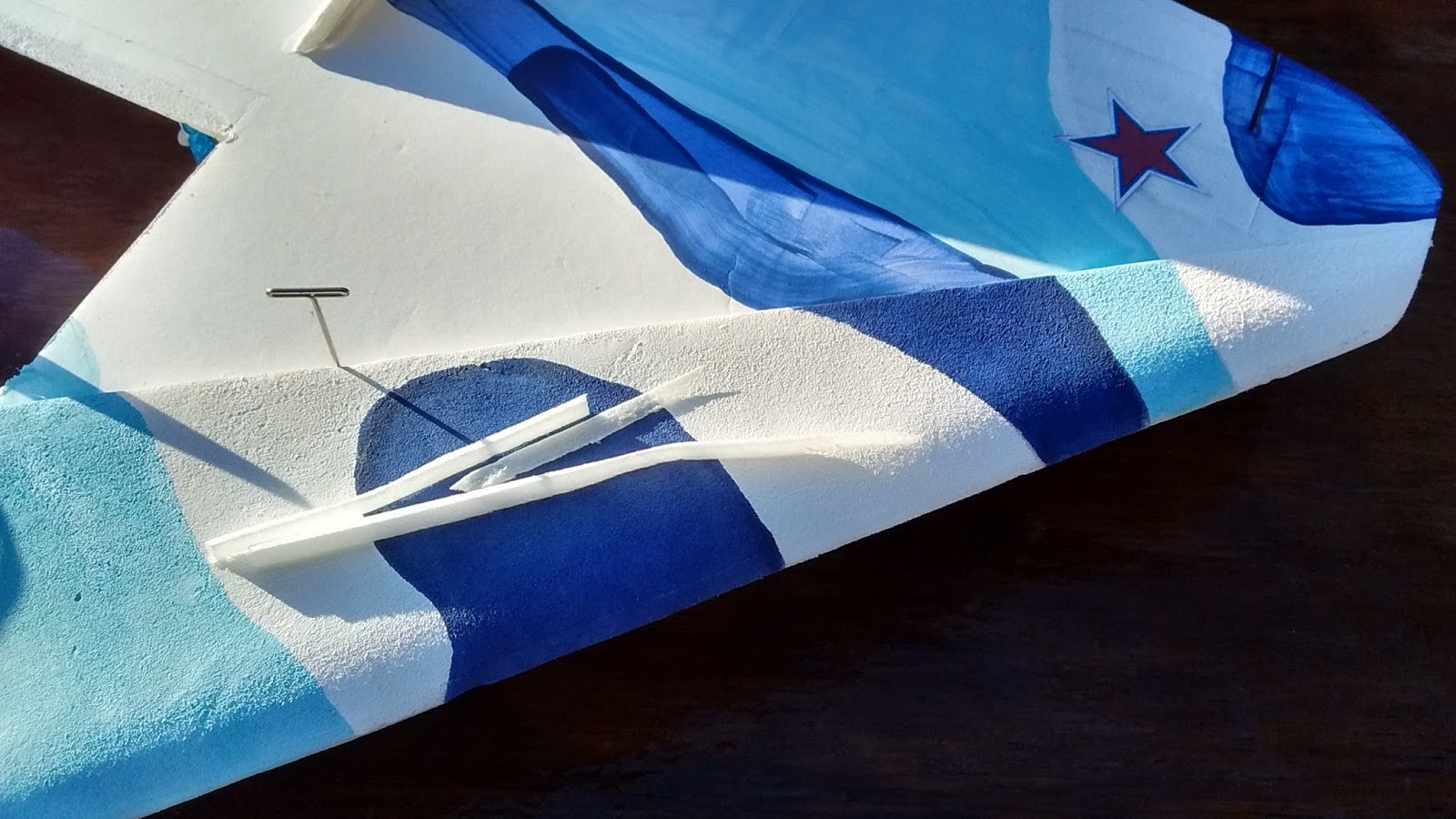
I had quite a bit of left trim in at the time, but that shouldn't have caused the rather aggressive wing dips and yaw that I was seeing, so after the second flight I decided to double check that the trailing edges of my KF4 airfoils on both wings were even. Low and behold, the trailing edge on the bottom KF on the left wing was about 1.5-2mm further back than the one on the top...OOOPs! 😬
How I determine this is I push a pin through the wing right at the trailing edge of the KF as you can see in the picture to see if the trailing edges are aligned. When I pushed it through on the left wing, there was foam behind it on the bottom, you can see the part I trimmed off laying on the wing.
Once this was trimmed off, the nasty tendency to want to dip the left wing went away, fortunately the RC Gods were with me yesterday and I didn't lose the plane due to my inattention to detail in that part of my build😳 Big lesson learned and wake up call😓
Control surface throws
A couple flights after I shot the video, I did zero out all the trim on my control surfaces and found that my right aileron was deflected up about 2 mm when it should have been dead center, so I zeroed that and it helped me remove quite a bit of the left trim I had been flying with. There is still some there, but not anywhere near as much.
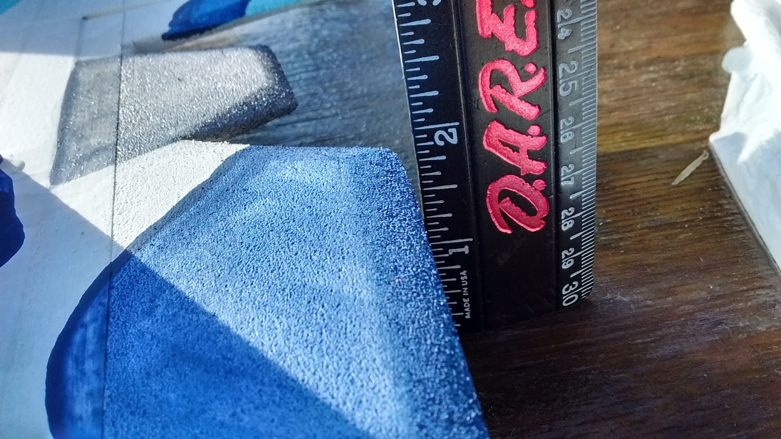
Here are my current throws which may get adjusted minimally as I get more used to the plane, but these seem to work best for scale flying and still allow me a little extra in the pitch if I need to avoid hitting something😲 Of note, I don't fly with a lot of expo, only 15% in the pitch and roll and 20% in the yaw, so the control surfaces react pretty quickly when I move the sticks. Pictures are below showing where I hold the ruler to measure for reference.
Pitch - 3/4" of travel one way;
Roll - 1/2" of travel one way in both the elevons and ailerons; and
Rudders - 1 and 1/2" one way.
Of note, the travel in the roll in the ailerons and elevons is equal. On most other planes, my aileron throw is considerably less (normally less than 50%) than my elevon throw in the roll axis. With these stealth style park jets, I find I need to have them closer to the same to get the rolls crisp and axial otherwise the rolls tend to be more of a barrel roll or the nose wanders around during the roll.
Launch
Launches were uneventful, I was a bit worried after downsizing and reshaping the vertical stabs and shortening the nacelles that I might have some torque roll issues, but none ever showed up. With the good mid range power of the EMAX RS2306 2750 Kv motor and the fact the plane is pretty light at 552 gr/19.5 oz, 50% throttle was sufficient to get it going and flying away nicely.
Turns
The T50 tracks really well in turns, in the calm wind conditions I had, I never really had to feed in any rudder input to keep the nose tracking true. However, it took me awhile to get the throws and my touch just right to keep it from "over banking". As I mention in the video, the battery sits up much closer to the wing plate, there is only about 3/4" between the bottom of the wing plate and the bottom of the electronics bay on this plane whereas with my modified F-22 V5, it is more like 1 and 1/4" which makes the F-22 more stable. Also, because I reduced the height of the nacelles, there is less resistance in the roll axis, so it sometimes wants to bank a little more quickly than a lot of other planes I fly. However, with time my thumbs will figure out the right touch😉
Rolls
As mentioned above in the section on throws, it did take me awhile to get the rolls sorted out to ensure they were balanced and axial. The T50 is very responsive in the roll axis and requires very little surface deflection to do a complete aileron roll.
Loops
As I mentioned briefly in the video, it takes a little gentler touch over the top of loops to let the up elevator input off at the right time. Since the battery does sit a little high in relation to the wing plate, the T50 is almost a bit "top heavy", so as it starts to go through pure vertical, it can fall over on it's back a little more quickly than some other planes, so when I was trying to go for a nice uniform loop, I had to be careful with this. Otherwise, the loop would look more like an egg where the plane went over the top too quickly and then the bottom of the loop would be wider.
Yaw response
Even though I did trim the rudder surfaces down quite a bit to accommodate my mod to the nacelles, they are still pretty responsive, of course I have pretty big deflection in them, but for keeping the nose true in turns, etc they do the job just fine. I like to pull up in the straight vertical and do stall turns to see how the rudders respond, thus far the T50 is not quite as quick in the yaw axis in a stall turn as the F22, but I can still get it to do pretty decent stall turns.
Slow speed
I took the plane up to about 100 ft a couple of times and reduced the throttle down to about 40% or so, it was not too bad, I had to be very careful in the turns or I would see adverse yaw on occasion. Essentially what would happen is I would be putting in control inputs to make a gentle turn in one direction and if the speed bled off too much, the plane would have a tendency to yaw in the opposite direction of the turn, sometimes quite aggressively. This was not a surprise as it is a common tendency with park jets with the stealth type wing like the F-22 and T-50. So lesson learned, don't get too slow in turns, speed management is crucial to ensure either the plane doesn't want to roll on it's back to suddenly yaw opposite to the direction of turn.
Cruising around
In the video I mentioned that this airframe style (T-50) likes to go fast. I didn't mean you need to fly it wide open all the time, it flies and behaves just fine at about 50-60% throttle all day long, but on occasion as the speed bleeds off too quickly or the throttle setting gets too low other than when coming in to land, it can misbehave somewhat😏
High speed
I would say RC Powers is correct in billing the T-50 as being faster than the F-22. The F-22 is pretty fast, but this T-50 is noticeably faster. Once I got the KF problem sorted out, it handled aggressive acceleration and full throttle runs just fine, I didn't see any torque roll, speed wobble or tendency to want to zoom or dive. Full throttle turns and aggressive vertical pulls were just fine, no bad tendencies, it felt locked in and solid at speed and the wing was strong, no flex even in high G turns or pulling out from loops and dives.
Glide/landing
The T-50 behaved itself well on approach to land, I did my normal approach routine, roll it out straight and level, chop the power and let it glide down at it's own rate from about six ft off the ground, feeding in a little bit of up elevator as needed. Once I had it balanced, it actually maintained a pretty steady and smooth rate of descent on it's own once the power was chopped. I fly with my brake off on my ESC, so the prop free spins as it is gliding, I have found this to give me the most stability. Then just as it started to break ground effect about 2 ft off the ground, I fed in just enough elevator to hold it off and it landed pretty smoothly on it's own. Once I fixed the KF problem I didn't notice any tendency for it to want to tip stall as it slowed down to land, which is good👍
So overall, the T-50 is fast, agile and very responsive, especially in the pitch and roll. Once I started to get the hang of it, it became more and more fun to fly with each flight although it did take a bit more dialing in than some other planes to get the CG and control throws just right. As I mentioned in the video, because of it's quickness, speed, adverse yaw habits if too slow in a turn and it's slight "top heaviness", I would not recommend this for a starter or even second park jet. Perhaps if your skills were coming along well or you had lots of flying experience before getting into park jets it might be a different story. I would say the F-22 is a bit more forgiving while still quick and aerobatic, so if you have never flown a stealth style park jet before, I would suggest flying the F-22 first perhaps with some of the mods I made as discussed in this video to help with stability.
Looking forward to many more flights with this little rocket of a park jet and as I get it dialed in completely and more comfortable with it, I will shoot some more video😊
In among all the holiday cheer, I managed to putter away a bit on my T-50 V5, mostly getting things ready before mating the fuselage to the wing plate. One thing I like to do is mark where my elevon control horns will go. Knowing that where I will be connecting the pushrod to the servo is approx 3/4" out from where the servo will be mounted in the side of the "nacelles", I use the slot that marks where the nacelle will fit into the wing plate as shown in the second picture.
Then using one straight edge as guide, I make a mark on the elevon on both sides so that I remember where the control horn will be mounted. I rarely use the control horn marks that are indicated on the plans as they rarely line up with where I want to put my control horns.
I used 150 grit sandpaper to taper the trailing edge of the wing, the leading and trailing edge of the prop slot, the leading edge of the horizontal stabilizer and all around the outside edge of the elevons to help keep things sleek. I like to do all this sanding before mounting the control horns, but I forgot to take a picture of that😏 While I can lay the wing plate flat is also when I sand the hinge tape on the ailerons and elevons so that it is no longer shiny and paint will adhere to it much more easily.
I also tapered the outside edge of the vertical stabilizers and added some bamboo skewers for extra reinforcement.
Before being able to join the fuselage to the wing plate, I needed to glue the front part of the wing plate on. You may remember that this part was cut out separately so that I could get the wing on a 20x30" sheet of Dollar Tree foam (DTF).
I start by taping the two pieces together as shown below.
I then hinge these two pieces open, exposing the edges of the foam as shown in this picture.
Then using 5 minute epoxy, I spread a fine layer on each side of the foam, then lay it flat with the tape down (I always put wax paper under it so that I don't have any ooze out and glue my wing plate to my work table). If any excess epoxy oozes out on the top as shown here, I take some scrap foam and spread it smooth ensuring any gaps between the two pieces of foam are filled.
Then another piece of wax paper goes on top of that seam and I weight it down with something so that the joint dries nice and flat.
In the next picture below the video, you can see that I have put the "insurance" tape on the bottom of the elevon hinge as I describe in this video at about the 7:50 mark.
Control horns mounted using epoxy.
So lots of "fussy" work done now, it is just a matter of mating the larger parts of the plane together, finish constructing the fuselage, attach the "nacelles" and "under rudders".
I have managed to keep slowly plugging away at this build around all the crazy Christmas and holiday activities that have been ongoing the past week😊 Here are all the parts finally cut out after all my measuring, calculating, drawing, etc.
In this next series of pictures, I discuss how I did the final sizing of my KF4 airfoils. First I taped the front piece of the wing plate on where I had cut this off on the plans in order to fit on the 20x30" sheet of DTF. Then, I laid out the template of the top KF I made from the plans on top of the wing plate and both of those laid on top of another piece of DTF so that I could trace the full top KF including the LERX.
Here you can see where I traced the portion for the LERX and where it meets the leading edge of the wing. I then placed the template from the plans back on this and traced out the entire top KF including the extra bit I needed at the wing root end to get the dimensions I wanted.
Full top KF not cut out. I then used this as a template to trace out another top KF and for the main part of the bottom KF.
Using the wing plate as a guide, I drew a line on the inner part of the slot that will accept the outer engine/nacelle tab as the bottom KF will be up against this at it's root.
Then I drew in all the lines and I had my bottom KF ready to cut out. I then used this as a template for a second bottom KF as well as for a template in the event I want to build another T-50 V5 and use the same KF size, I won't have to go through this fuss again.
Here is the bottom KF sitting on top of the top KF, important to ensure that they are uniform where they will be on the wing. They can also be trimmed slightly if need be when installed on the plane.
I cut out my elevons all in one piece and will keep them that way until I sand the leading and trailing edges on the wing plate before mating to the fuselage. I scored where they will be cut later after sanding as indicated by the red line in the picture.
Before assembling anything else, I made sure to make templates from scrap foam for all those main parts I modified, vertical stab, both KF airfoils and the elevons. Again, this will make building another much easier if these mods work out well.
Using the wing plate as a guide where I had already marked the CG, I marked this on my top KFs for reference. I like to hold my planes upside down when I determine the CG before maiden, I just find it to be a bit easier and more accurate. Of course this gets fine tuned after the maiden and during the "dial in" process.
Now that I have the KF airfoils figured out, I can trace where the trailing edge will be on the wing plate top and bottom since the paper will be removed forward of the trailing edge to keep things lighter, allow for good glue bond between the wing plate and KF and keep the leading edge of the wing more sleek.
In the next phase, I will trim off the paper from where it needs to be trimmed on the wing plate, ailerons, vertical stabs, hinge the elevons and ailerons, install the reinforcement in the wing and vertical stabs. Fussy work, but once that is all done, the rest of the build should come together quickly😊
I'll just keep plugging away as there is still some holiday cheer to be had over the next week!
Last evening and today were busy getting the plans taped together, doing some measuring, drawing and even quite a bit of math...brain is tired now!😖 I think I have the vast majority of the work done to satisfy my planned modifications, so it will be much easier to start cutting foam and get building😊
I'll try to keep this organized and explain in detail what I did as well as why and how I did it, so this will be a bit of a lengthy post, but should be lots of pictures for distraction😉 Either way, you might want to grab a snack and a beverage, or read it in small chunks! This is normally the longest part of the build process for me when I am doing several mods on a plane, lots of measuring, figuring, drawing, redrawing, etc, but once I am happy with it, the rest goes along a lot quicker and smoother😊
I'll start with the wing plate since that is the most detailed and required the most measuring and drawing to accommodate my planned modifications.
One of the things common to all the V5s I have built is the wing plate is in two separate identical pieces. I prefer to tape these together first before putting them on the foam and cutting, especially if I am going to make modifications as you can see above in this picture. I have roughly laid out my carbon reinforcement ahead and behind the prop slot and along the elevon hinge line. One main difference between this and the F-22 is that she has a little extra "junk in the trunk" behind the wing as it is much wider than the F-22 V5.
In this current size, while I could lay it down on a 20x30" sheet of Dollar Tree foam (DTF) to get the 27" wingspan in one piece, it is far too long and needs to be cut in a couple of spots. I chose to draw lines here in front where the LERX (leading edge root extension starts to angle back more dramatically. This piece will get glued back to the main wing plate at a later point in the build once other things have been completed with the main wing plate.
In the rear, it made sense to cut off the elevons as I will be making those out of Depron anyway.
This will leave me with a main wing plate piece that is about 19" long, so easy to fit across the 20" width of a full sheet of DTF and have that all one piece.
Motor mount/prop slot mod, etc
As I mentioned in part 1 of this series, one of the mods I will make is to move the motor further forward by 1", primarily to compensate for the weight of the paper on the DTF behind the trailing edge of the KF and also hopefully to help the plane be more balanced and rotate more easily in all three axes.
There is a lot going on in this picture above, so I'll try to make sense of it. Originally, when I drew the sides of the prop slot, I had forgotten to widen it out so that it will be even with the outside parts of the "engines/nacelles" underneath. The black dashed "-" lines indicate where that will be, drawn by lining up the slots fore and aft on the wing plate to see where those will be. The lines that are "squiggled" out in black were my original lines and it made for a very narrow prop slot, maybe 6 and 3/8" which caused me to remember I could widen it out.
Hopefully you can see where I moved the motor mount forward 1" and also trimmed 3/8" off the leading edge of the prop slot to accommodate shorter quad racing motors. I always like the back of my prop slots to be a straight line, so drew that in accordingly. Gives my prop lots of room to "breathe" and perhaps it is not aesthetically pleasing, but hopefully gives me best performance from my prop and motor.
You can see where I put my carbon ahead of the motor mount, I will be using a piece of 3mm carbon tube as shown below. It is recycled out of a previous plane, so I need to remove the foam and glue residue before it goes into this plane. If you look to the right of the motor mount area below the carbon tube, I have drawn a small 1/4" square, this will accept a 1/4" tab from the top of the fuselage. I made this change so that nothing would interfere with the carbon tube, it is primarily for alignment of the top of the fuselage, not for strength, so should be adequate. If you look at the far right, I also modified the slot that will accept one of the tabs on the "engines/nacelles" to accomplish the same thing. I will place the carbon tube so that it runs right through the dead center of the "CG spectrum" that RC Powers puts on their V5s. This way I know that where this tube is will be my starting CG point for the maiden flight.
Reinforcement of the wing plate
As you can see in this group of pictures, I will be using carbon to reinforce the wing plate in three areas, a 13" piece of 3mm carbon tube ahead of the prop slot as shown above. I'm hoping that since this will be "locked in" under the KF4 airfoils it will give sufficient strength without adding the extra weight of 4mm carbon rod. Plus I already had a piece that fit perfectly recycled from another plane😉
For the main wing spar, I am using a 25 and 1/2" piece of 4mm carbon rod for maximum strength across the widest part of the wing, again, this piece was recycled from another plane, glue and foam residue need to be removed.
On the back plate ahead of the elevon hinge line, I am using a 15 and 1/2" piece of 3mm carbon tube. Since the "nacelles/engines" don't extend all the way back due to the unique "under rudders" of the T-50 and it is pretty wide back there, I wanted extra strength to prevent torsional twist caused by the elevons.
Aileron mod
Like I did with the F-22 V5, I wanted to increase the size of the ailerons. Due to the width of the back end of the T-50, the trailing edge of the wing is not that long, only 17.5 cm. I "showed my work" as you can see, 60% of 17.5 is about 10.5 cm which is what I used for the span and I increased the depth/chord to hopefully have enough control surface area for the ailerons to be effective. Of note, I find it easier to use metric when I need to take percentages of things or work out ratios. Just much easier for me when things are all based on 10 or decimals of 10 than percentages of inches😃 Although I'm still a bit "old school" and use inches when it suits me😉
Elevon mod
As I mentioned in Part 1, I wanted to add the "boom" to the center of the elevons not only for scale looks, but to add a bit more surface area to the fairly tiny stock elevon surface.
I borrowed from the NAMC Mig-FA a concept stealth plane my NAMC partner Stephan designed and I helped with the test and validation phase. Plans are free at the link or you can e-mail me at scott.parkjet@gmail.com and I can send you the PDF files. It is a concept plane based on the T-50 with a 27" wingspan, so these worked out pretty well I think and will hopefully add more authority to the elevons and a bit more "cool factor" to my plane😎
Mods to the nacelles/engines
Since I moved the motor ahead by 1" and will be using a shorter quad racing motor, I needed to trim the back of the nacelles so that they wouldn't interfere with the prop.
Also, I modified the tab where it will go into the slot I already modified on the wing plate.
I will not be putting my servos in the indicated locations. I will have to put my rudder servos behind the prop slot due to the "under rudders", my aileron and elevon servos will go as far forward as I can get them to shift more weight forward of the CG.
Fuselage modifications
Again, due to the movement of the motor and mod of the prop slot, the fuselage also needed to be adjusted. Back of the hatch to the electronics bay shorted 1 and 3/8" inches to avoid interference with the prop slot.
On the fuselage, I moved the center where the motor mount supports go forward 1" and the top piece of the fuselage 1 and 3/8" so as not to interfere with the prop slot. You can also see where the pencil is pointing I modified the tabs to fit into the slots I modified on the wing plate.
KF airfoil modification
Normally if I am going to modify a KF airfoil, I will cut one from the plans out of scrap foam. I always like to start with the top as once I get that sorted, I can easily make another of proper size and then size the bottoms ones later on (I will show how I do this later in the build process).
I will then trace it out on the wing plate plans so that I have some reference to work with to start measuring and calculating, shown highlighted in yellow below. This actually shows the final size of my KF after all my math, but hopefully you get the idea😉
So this next part might be a little difficult to follow, I'm kind of "winging it" (pardon the horrible pun 😏), but I think it should work. The T-50 has a very unique wing shape so I had to make some compromises.
I started off measuring the rough chord of the wing where it would be meeting the fuselage. You will note in the picture above, I don't factor in the extra bit that goes forward over the LERX (leading edge root extension)/intakes.
I also didn't factor this little bit into the wing chord, the triangular area roughly marked in blue
Where you see the metal straight edge in this picture is essentially where I marked the trailing edge of the wing.
So measuring from the top point of the KF to where my "trailing edge" is (indicated by the blue arrow), this measures 40 cm. Since I like to have 40% of chord at the wing root on my KFs, 40 x .4 = 16cm, hence why in the picture of the KF above I have marked to add 1 cm when I cut out my own.
The RCP ones were very close and fortunately the trailing edge of the KF is right on my modified prop slot leading edge.
At the wing tip, I also had to do a bit of compromising. The very tip of the wing is actually quite narrow on the T-50, so if I took 35% of that, I feared my KF might be too narrow at the wing tip to function the way I want. So I measured the very wing tip at 4.5 cm, then drew the blue line where the tip of the wing area is a bit wider (10 cm), took the average of those at 7.5 x 0.35 = approx 2.5 cm which luckily enough is what the stock measurement is on the RCP plans, so I'll go with that.😊
As mentioned earlier, once I get the wing plate cut out of foam, I will demonstrate how I draw out the rest of the top KF and then size the bottom KF so that they will be proportional on the wing.
Vertical stab modification
Again, I hope my math and methodology make sense here on how I modified my vertical stab, I used a little bit of math and some "artistic licence", but I think/hope the final product will look good and be functional. Looking at the current vertical stabs, they looked too much like those on the F-22 and not like those on the T-50 for my liking. I wanted mine to have the more unique angle and proportional size that I see in this diagram.
Having the plans to the RC Powers T-50 V1 from a long way back (unfortunately no longer available), I printed off one from those plans as a starting point. I like the more scale size and shape of this stab.
So I started playing around with a few numbers knowing to match a 27" wingspan, the V1 stab would have to be about 13% bigger. Then looking at the current size of the stock V5 stabs, I took an average of that, mixed in a little "artistic licence" on what I thought looked good and came up with the dimensions below using the same angles as on the V1 stab. I estimate I have reduced the overall size by maybe 10-15% and made it look what I hope I will be a bit more scale, we will see. I will cut out an extra one when I build the plane to have as a template for later builds in the event this works😊
Motor shims
This last part really has nothing to do with the mods, more of a big lesson learned or word of caution. In the V5 series of planes, RC Powers came up with the idea of using foam motor shims to adjust the motor location to make it easier to balance the plane (I "think" that is what the logic is anyway😐), if you watch this video at about 0:50, you will hopefully see what I mean.
I tried this when I built my first V5, the Su-27 and I found these foam shims to be a significant point of failure. When I would epoxy my wooden motor mount to the flat face of the shim, over time, they would rip apart, the epoxy actually pulling a thin layer of foam off with it as this is not a strong bonding method for the epoxy.
I brought this to RC Powers' attention via e-mail, however it was not really addressed, fair enough, their designs. However, from my personal experience, I would steer clear of using these foam shims on any of your V5 planes lest you risk your motor coming off in the air or you could end up having to continually glue it back on over time creating hassle for you and more weight to your plane😒
Well, hopefully you are still with me, follow on installments of this build log should be much shorter and less detailed...fingers crossed!